Serial Communication
UART vs USART
- UART Peripheral supports only asynchronous mode
- USART supports both asynchronous and synchronous modes.
- You can use USART module both in synchronous mode as well as in asynchronous mode
- There is no specific port for USART communication. They are commonly used in conjugation with protocols like RS-232, RS- 434, USB etc.
- In synchronous transmission, the clock is sent separately from the data stream and no start/stop bits are used
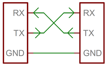
UART Pins
UART Frame Formats

- Start Bit: To start the transfer of data, the transmitting UART pulls the transmission line from high to low for one (1) clock cycle.
- Data Frame: It can be five (5) bits up to eight (8) bits long if a parity bit is used. If no parity bit is used, the data frame can be nine (9) bits long.
- Parity: After the receiving UART reads the data frame, it counts the number of bits with a value of 1 and checks if the total is an even or odd number. If the parity bit is a 0 (even parity), the 1 or logic-high bit in the data frame should total to an even number. If the parity bit is a 1 (odd parity), the 1 bit or logic highs in the data frame should total to an odd number.
- Stop Bits: To signal the end of the data packet, the sending UART drives the data transmission line from a low voltage to a high voltage for one (1) to two (2) bit(s) duration.
UART Frame Protocol
One key feature that is available in UART yet not fully used is the implementation of a frame protocol. The main use and importance of this is an added value for security and protection on each device.

- Header: Header is the unique identifier that determines if you are communicating with the correct device.
- Command: Command will depend on the list of command designed to create the communication between two devices.
- Data Length: Data length will be based on the command chosen. You can maximize the length of data depending on the command chosen, so it can vary based on the selection. In that case, the data length can be adjusted.
- Cyclic Redundancy Checking: The cycling redundancy checking formula is an added error detecting mode to detect accidental changes to raw data. The CRC value of the transmitting device must always be equal to the CRC computations on the receiver’s end.
Advantages
- Only uses two wires
- No clock signal is necessary
- Has a parity bit to allow for error checking
- The structure of the data packet can be changed as long as both sides are set up for it
- Well documented and widely used method
Disadvantages
- The size of the data frame is limited to a maximum of 9 bits
- Doesn’t support multiple slave or multiple master systems
- The baud rates of each UART must be within 10% of each other